Guest

Software

View our product selection

Upgrades

Upgrade pre-owned software

Training

Comprehensive End User Training

A-PROP v.3.0 Software

A-PROP

[[ updated_price | currency ]] plus [[ annual_price | currency ]] annually


In order to purchase software, you must either login, or register a new account.

Login Register
 Download Free Trial

Aprop Overview

Section Properties made easy...

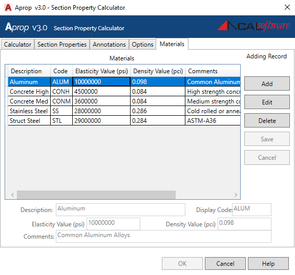
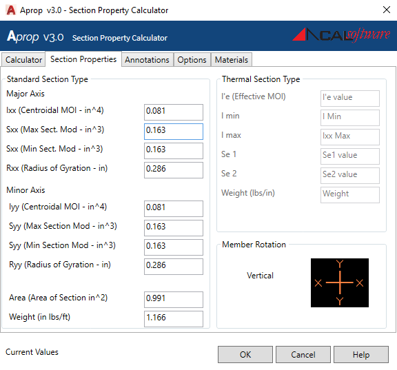
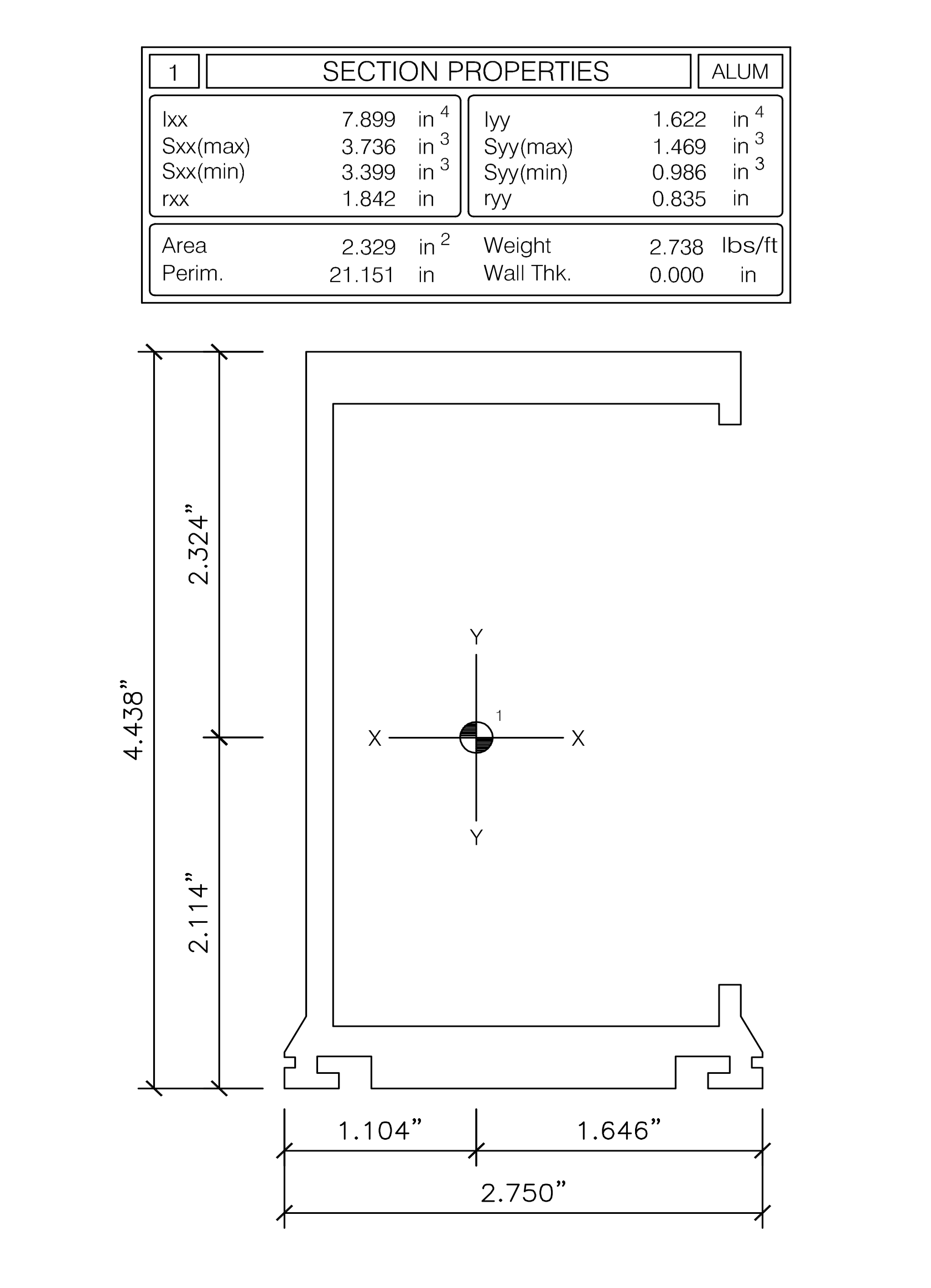
Aprop is an AutoCAD Lisp* program which calculates the structural section properties and extrusion information utilizing an integration of area method about lines and arcs of a given shape. The utilization of this method provides a level of accuracy not found in similar programs and instantaneous results. Aprop can accommodate solid or hollow shapes and is unique in providing options for utilizing steel or aluminum, assemble or composite addition of different members.

*AutoCAD LT is not compatible with Aprop

Key Features

  • Application launched from desktop and AutoCAD toolbar.
  • Compatible with AutoCAD 2016-22
  • Graphical user interface. Totally interactive. “Dialog box driven”
  • User defined elasticity and density variables allowed; aluminum, steel, or user defined.
  • AAMA Poured and Debridged Equivalent Composite routine.
  • Composite and assembly properties for build up sections.
  • Custom template provided with individual preferences and custom tailoring
  • Wind load Charts for custom deflection criteria
  • Metric units output, American unit output, or both unit system output
  • Scalable feature and automatic sizing for large oversized shapes and assemblies.

Shape Guidelines

The shapes being analyzed need to be closed polyline entities (including circle and ellipse) so that the area can be calculated. The shapes need to be 2D profiles; therefore, AutoCAD regions are not usable by the current version of the APROP software.

Likewise, the shapes being analyzed cannot be AutoCAD blocks or groups. They must be exploded or reduced to single entities before selection and calculation.

After selecting a shape, all calculations are made based upon current setting of the drawing. In the current version of APROP, shapes are assumed to be drawn in English units, but you have the option to output in either English units or metric units, or both.

Features Coming Soon!

  • Mirror image property generator for effective ry evaluation
  • Torsinal J Constants for open and closed shapes
  • Plastic Zxx section modulus
Section Properties

From the Command Line (keyboard)

  1. The user can start a new 8 1/2” x 11” drawing using the template “APROP.dwt which sets up all layers, styles, and dimensions styles required by typing “STARTNEW” at the command line prompt.
  2. The template will load with a simple border and a Model, Paper and Windload tabs. See figure (right)
  3. The calculator program can be initialized by typing “APROP” launching the user interface dialog box. See figure (left)
Loading Manually

From the Autodesk Ribbon (toolbar)

  1. The user can start a new 8 1/2” x 11” drawing using the template “APROP.dwt selecting the blue NEW ICON.
  2. The Aprop Primary dialog box should appear, see figure 1 (left). You are now ready to start the Section Property calculation
  3. The calculator program can be initialized by selecting the blue APROP ICON launching the user interface dialog box. See figure (left)
Section Properties

Sectional Properties Display

  • The tab labeled “Section Properties” will provide current calculations of section properties, see Figure 1 (left).
  • This tab will not be available until you have selected the primary shape. If the shape has an area that can be determined, the calculations are made and printed to this tab. The shape orientation as selected on the “calculator” tab is displayed on this tab for reference.
  • These boxes are read only and date is only retained until some other shape is selected. As other shapes are selected, the section properties displayed in this tab indicate a running total, or current calculation based up on all previous information.
Output & Concluding the Calculation Run

Output & Concluding the Calculation Run

  • After you press “OK”, the calculator concludes and APROP will give you an output, see figure 2 (right) for a typical output.
  • The dimensions, centroid, title block information, you company logo and address information has all been added to the drawing.
  • You can move any of the data supplied by the APROP Calculator. Review the drawings and move the entities around to make them more readable. At this point you are free to move entities to any layer, change color, line type or text style. Since it is a standard AutoCAD drawing, you can add any additional information to the drawing as required.
Annotations

Annotations Tab

  • The tab labeled “Annotations” will provide editing of the shape, manufacturing, project, and company information used as output for the APROP Calculator, see the above example.
  • In the current version of the software, this information will be printed in the title block and in the address block, provided those options are selected.
  • This tab contains edit boxes for annotation data. The program uses this data to print in the title block and address block of the current Calculator Run. It will retain the data to be available for the next run. Remember to review this data at the beginning of each run to ensure accuracy.
Options

Options Tab

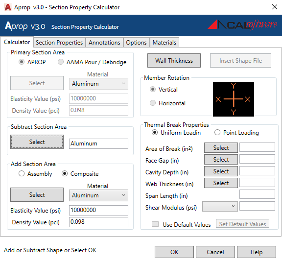
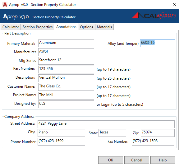
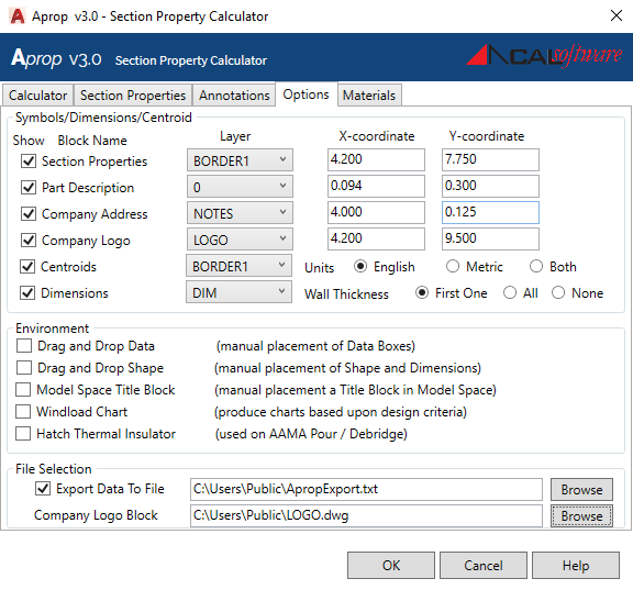
The tab labeled “Options” provides the space to declare options that will modify the output of the APROP Calculation run.

Symbols and Placement

  • The first frame entitled Symbols/Dimensions/Centroid” gives options for Dimensions and Symbols. Refer to the above figure.
  • The first column titled “Show” is a toggle to turn “On” or “Off” the items indicated. If toggled “On” then the columns to the right of that item are enabled to you to declare which AutoCAD layer and the X and Y coordinate where you want that item placed.
  • All items, symbols and dimensions can always be changed after the Calculation run.
Materials Tab

Materials Tab

  • You can add or edit any material types used by the APROP program by going to the “Materials” tab on the primary dialog box, see the figure above
  • The tab allows you to store any materials you wish for use with the APROP Calculator. The drop-down lists on the “Calculator Tab” will be populated by the database created and maintained by this tab.
  • When you enter this tab, the edit boxes at the bottom of the dialog box are disabled. The buttons to the right of the dialog box will allow you to add new materials, delete materials or edit existing, listed materials. When you press one of the edit buttons, the edit boxes at the bottom will then be enabled.
Windload_chart
Winload 2

Wind Load Charting
  • On the “Options” tab there is a check box to enable the feature of calculating Wind Load Graphs of the shapes where APROP has just calculated the section properties.
  • When selected, it will automatically produce wind load charts after conculding the section properties calculations.
  • APROP will open up a new page in AutoCAD’s paper space labeled “Wind load” and will have to printed separately from the section properties page.
  • The charts produced by this Wind load Charting feature are based upon calculations for a single span with uniform loading conditions.
  • When the Wind load Charting Function beings, it displays a dialog box for user input.
  • After the chart is drawn, see figure 2 (right), and you need a chart using different input data for calculations, then re-run the Section Property Calculator again and make different selections when the Wind load Charting dialog box is displayed.